Overview
Cave radiolocation allows explorers to determine the position of underground cave passages from the surface by detecting magnetic fields transmitted through rock. While radiolocation has a long history in dry caves, its application underwater presents unique challenges: transmitters must be small enough for divers to carry, self-levelling to avoid manual adjustment underwater, and robust enough to withstand the demands of cave diving.
The original “Pinger” system was developed by Ken Smith in 2000 to address these challenges. I collaborated with Ken to develop Pinger 2.0, a complete redesign using modern microcontroller technology and improved coil designs. The system has been successfully used at depths exceeding 90 metres through rock.
Technical Improvements
Software-Defined Transmitter
The core improvement of Pinger 2.0 is its software-defined approach to driving the resonant coil antenna. By using an ESP32 microcontroller rather than analog circuitry, the transmitter gains:
- Real-time frequency tuning: The firmware can adjust the drive frequency to match the coil’s resonant frequency
- ADC-based feedback: Current sensing through the coil driver allows automatic detection of the optimal operating point
- Configurable beep patterns: Transmission timing and patterns can be modified in firmware
- Field programmability: Settings can be adjusted via USB or Bluetooth without hardware modifications
The ESP32’s dual-core architecture is critical for this application. One core is dedicated to generating the precise drive waveform, which has hard real-time constraints to maintain resonance in the coil. The second core handles housekeeping, sensor reading, and communication.
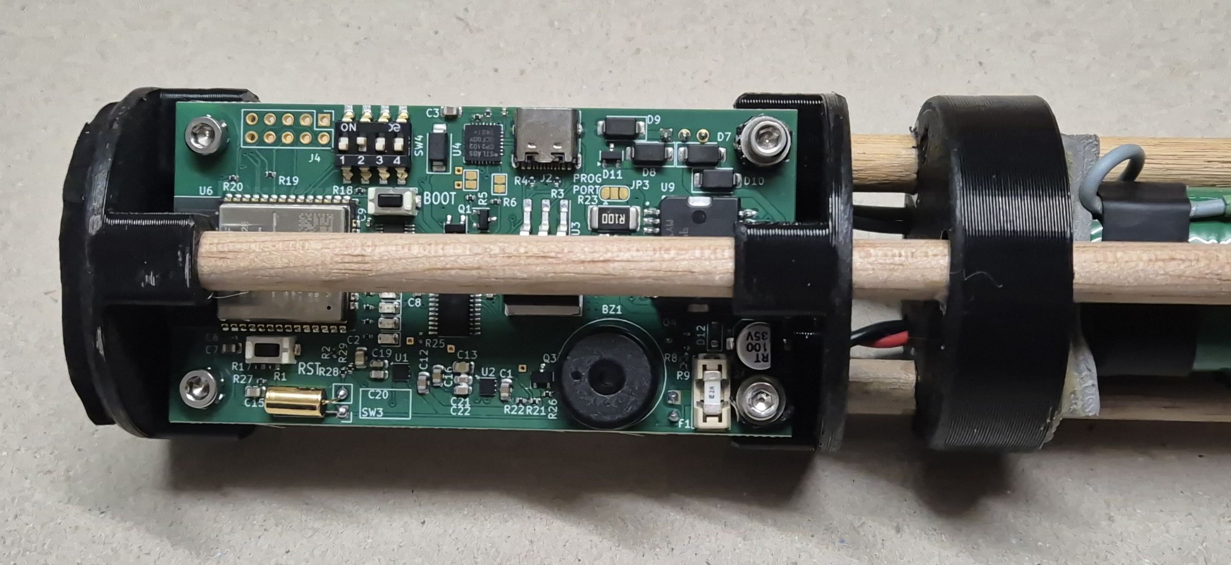
Figure 1: The Pinger 2.0 control PCB mounted in the transmitter frame with ferrite core antenna rods. The ESP32 module is visible at center, along with the buzzer, DIP switches for configuration, and USB-C port for programming.
Custom PCB Design
I designed a custom PCB optimized for small-batch fabrication, with surface-mount assembly handled by the manufacturer. Key features include:
- L298 H-bridge driver for efficient bipolar drive of the transmit coil
- ADS1115 16-bit ADC with programmable gain amplifier for current sensing and battery monitoring
- BMA400 accelerometer for orientation detection and tap-based user input
- Reverse polarity protection using a MOSFET-based design that doesn’t require fuse replacement after backwards battery insertion
- TVS diode protection against high-voltage transients from the coil
The board runs on four 18650 lithium-ion cells, providing higher voltage (nominal 14.4V) than the original design’s eight AA alkaline cells.
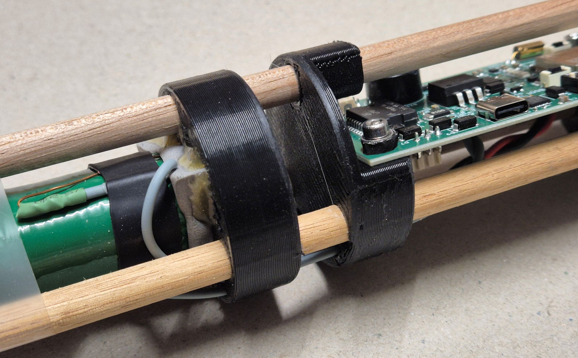
Figure 2: Assembly showing 3D-printed support discs, wooden dowels supporting the ferrite core rods, and 18650 lithium-ion battery pack.
Auto-Tuning Capability
The combination of ADC feedback and software-defined drive frequency enables automatic coil tuning. By sweeping through a frequency range and recording the current drawn at each frequency, the resonance peak can be clearly identified. This bypasses manual tuning with signal generators and allows compensation for thermal drift and component aging.
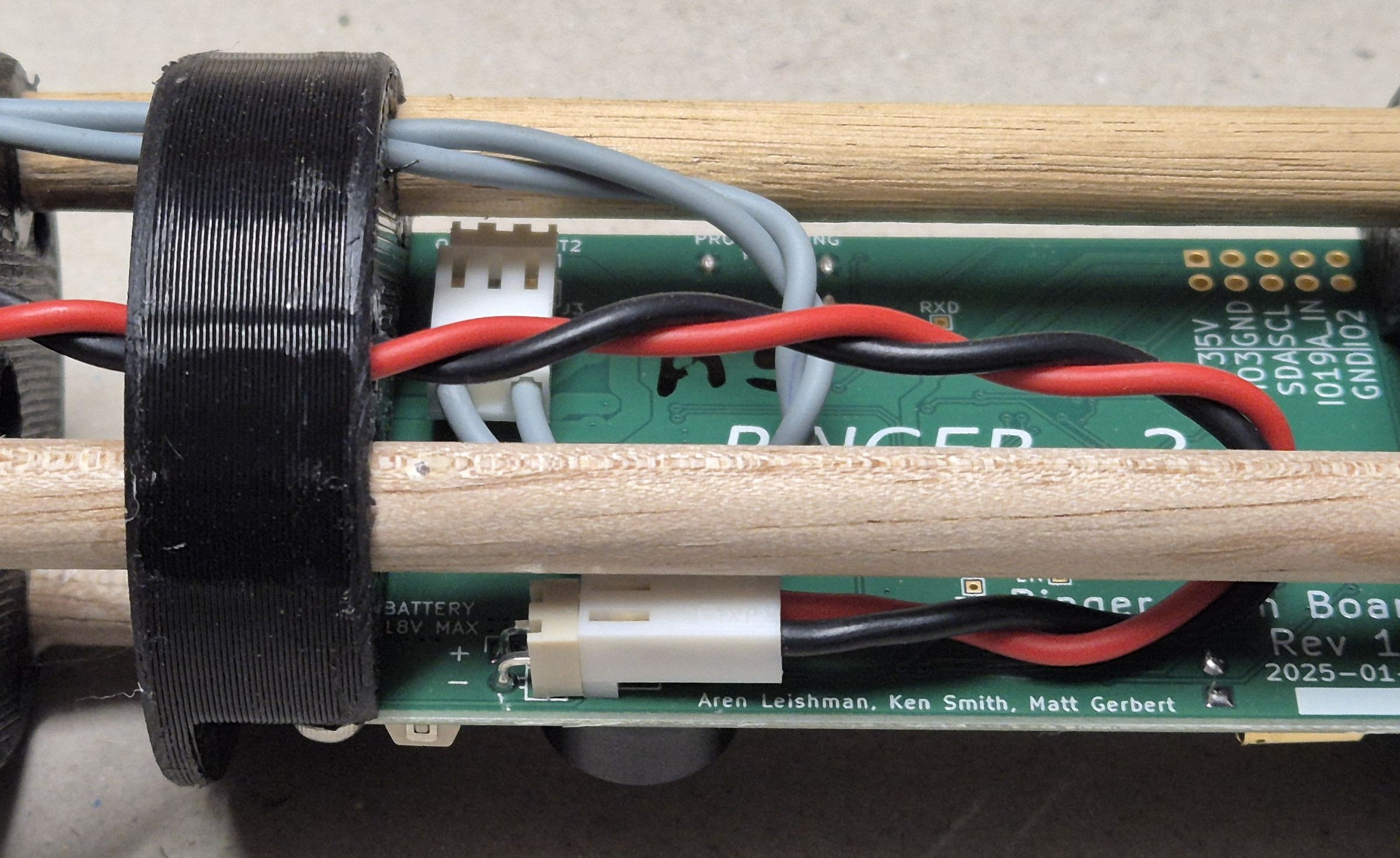
Figure 3: Wiring connections between the transmit coil and control PCB. The board silk-screen shows the project collaborators.
System Architecture
The transmitter architecture separates into power distribution and data distribution networks:
Power Network:
- Battery pack (4S 18650 lithium-ion)
- 5V regulator (powers buzzer and coil driver)
- 3.3V regulator (powers microcontroller and sensors)
- Switchable 5V rail for power saving during sleep
Data Network:
- ESP32 microcontroller (dual-core, WiFi/Bluetooth capable)
- I2C bus connecting ADC and accelerometer
- DIP switches for hardware configuration
- USB-C for programming and serial communication
- LED indicators and buzzer for status feedback
The accelerometer enables wake-on-orientation, allowing the transmitter to sleep during transport and activate only when deployed in the correct orientation underwater, though the tilt switch has also been retained.
Publications
This work has been published in the Cave Radio & Electronics Group (CREG) Journal, see the publications page for more information.
Future Development
Active development continues on several fronts:
- Regenerative receiver circuits: Using positive feedback to increase effective Q without the weight penalty of larger coils
- Two-way communication: Allowing surface operators to signal back to the underwater unit
- Enhanced power management: Switching to switch-mode regulators for improved battery life in standby
- Environmental logging: Using the ESP32’s flash storage to record depth, temperature, and orientation data
Availability
The hardware designs and firmware are available on request for researchers, cave diving groups, and anyone interested in radiolocation technology. The system uses the Arduino framework, making it accessible for modification and extension.